How to build a holodeck, week 29
This week, I’ve finally written my own meshing solution. Read on for details!
SharpChisel, V0.01
So, summer holidays are over, and it’s back to the coal mines - or in my case, the garage - to get cracking on capturing reality.
I’ve spent a few months now messing around with the Tango for capturing textured scenes, which is super-cool - but there’s a set of problems that I’m just not easily able to resolve with the Tango (mainly down to the quality and control of the camera feed, but also somewhat down to the results I get back from the depth scanning).
My ideal solution would be a pointcloud-to-mesh or depth-image-to-mesh process that works on arbitrary depth feeds from any device, written in C# (so I can use it on any platform that works with Unity). I’ve yet to find that - all the solutions I’ve used up to this point are either platform-specific (Tango’s Chisel) or require a load of hoop jumping to get them to work across multiple capture platforms (e.g. OpenCV), or they are locked to a specific scanning device.
So, the last few weeks, I’ve bitten the bullet and written my own depth-to-mesh solution. Using OpenChisel as a reference, I’ve created SharpChisel from scratch. OpenChisel is an open-source version of the proprietary Chisel implementation.
After about a week of reading and writing, I had something that looked like it should be functional, but without any deep understanding of what any of it meant. I then spent this week actually getting things to work, which has meant going through every function, looking at the inputs and outputs, and piecing together the flow of data through the process.
Mid-week, I got to the point where I had a single frame captured from the Kinect depth camera being converted into a voxel-field representation. You can see my orange chair (in this case, though, it’s grey - the depth image in this scene is coloured white up close, black far away, and yellow where there’s no valid data). The resulting voxel space is shown below the depth scan.
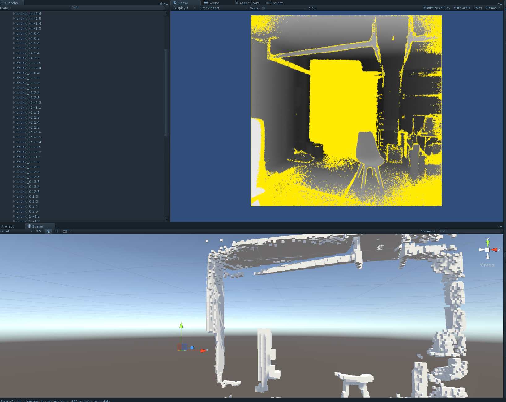
The whole middle of the scan is missing, due to math errors. A bit more messing about, and I managed to fix this:
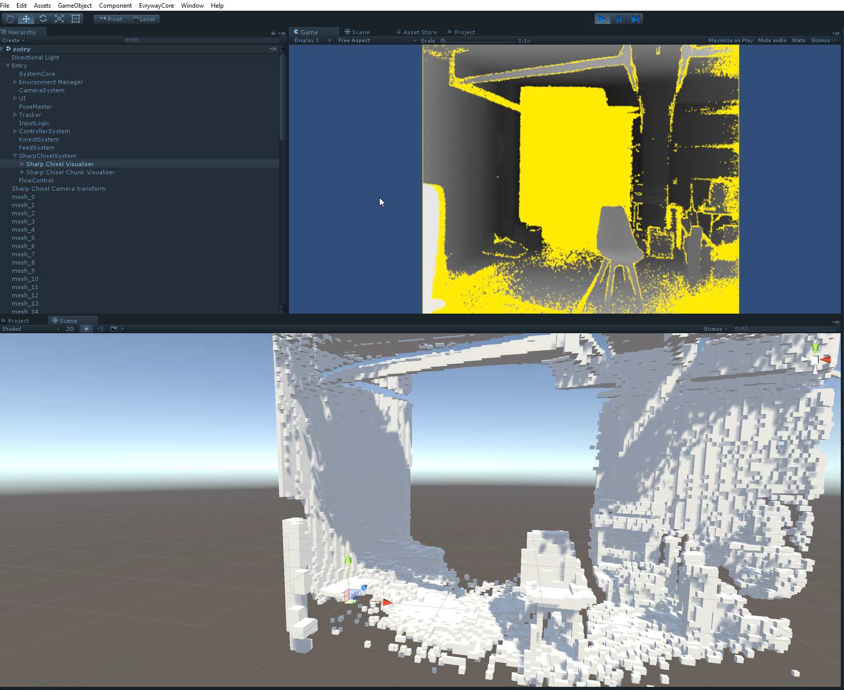
A wild chair appears!
You can make out the outline of my beer kegs and my brother’s workbench resting against the back wall if you look really closely.
The voxel space is currently 4cm granularity, and each chunk in the Chisel mesh is 16^3 voxels (so each chunk has 4096 voxels in it).
Each voxel represents a depth value - in this case, the result of a Truncated Signed Distance Field, or TSDF, value. Each voxel basically does a raycast into the depth image, and sees if there’s a depth value close enough to the voxel to matter to the voxel (“close enough” is the truncated part of the TSDF - if the depth image is 4m away from the camera but the voxel is 3m away, then the depth value is not relevant to the voxel).
If the depth value is within the truncation distance, then we store the “surface distance” (the difference between the voxel centre’s distance from the camera, and the depth distance in the depth image on the ray from the camera through the voxel). if this difference is negative, then the depth image point is closer to the camera than the voxel centre, and the voxel is “inside” the depth surface. if this difference is positive, then the depth image point is further away from the camera than the voxel centre, and the voxel is “outside” the depth surface.
This next image shows this with red voxels being “positive” (i.e. outside, or in front of, the depth surface) and green voxels being “negative” (i.e. inside, or behind, the depth surface).
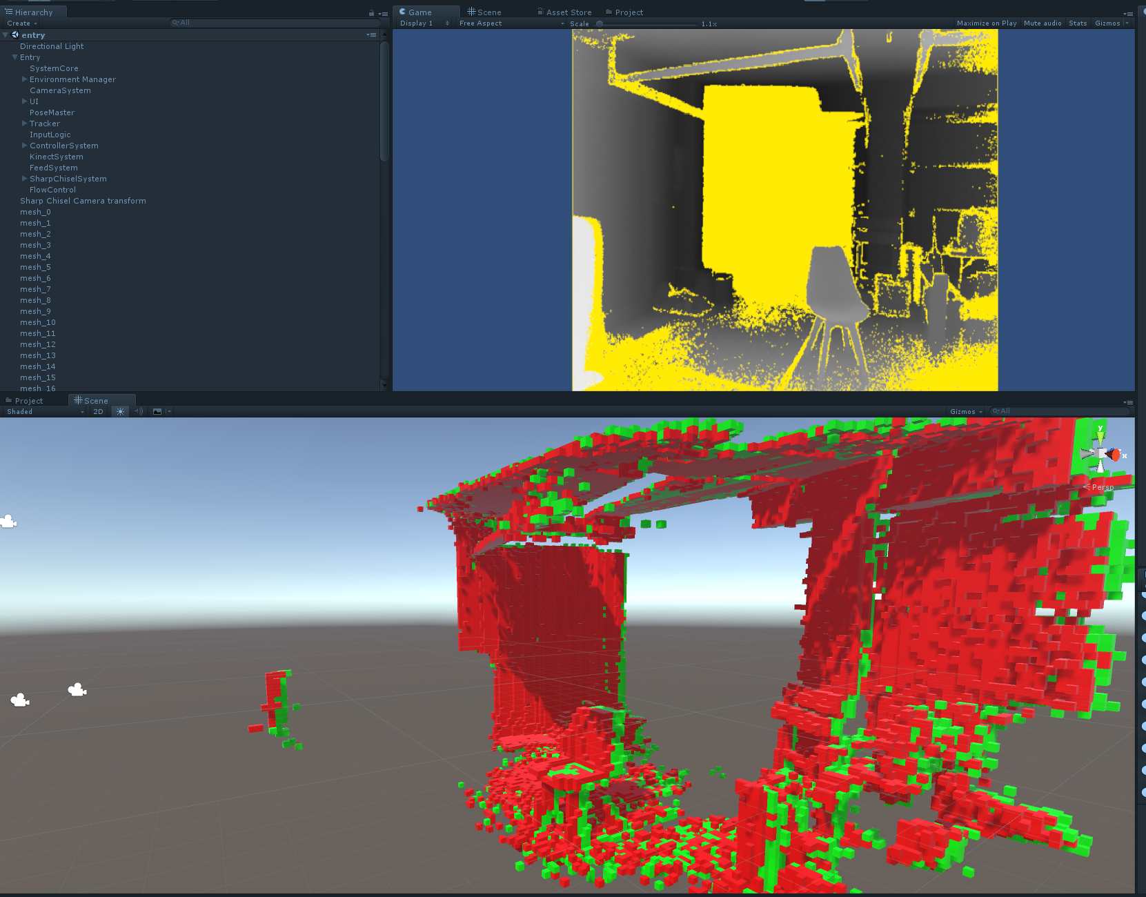
This is a slightly different angle onto the scene, but you can make out the chair in the bottom left, and the folded workbench in the middle.
Marching Cubes
As previously discussed there’s loads of ways to convert point-clouds and depth images into meshes, but probably the simplest solution to implement is Marching Cubes. this looks at cubes made out of each group of 8 voxels, using the TSDF value in each voxel as the corner of the mesh cube. Then, depending on whether the TSDF value is negative or positive, it puts triangles into the cube to represent the surface of the signed distance field.
The OpenChisel source contains a marching cubes implementation, which I mostly re-used as the basis for my implementation. I’ve done some re-ordering of all the components in the vectors and the like to make my implementation a bit more Unity friendly, which means the data tables that come with most Marching Cubes implementations (which seem to be coming from this paper by Paul Bourke ) are not in the right order for my corners - I do mapping between my ordering and the canonical ordering on the fly right now, a bit more effort will get me my own table data.
Yesterday, I finally got a valid mesh coming out the other end of a scan using the Kinect V2 camera, which has made me super-happy.
The results are not great, but they are visibly working. Here, I’ve re-coloured the depth image so that the depth data from 0.5m to 1.5m is red, 1.5m to 2.5m is green, 2.5-3.5m is blue, and 3.5m-4.5m is yellow. Duff data is black.
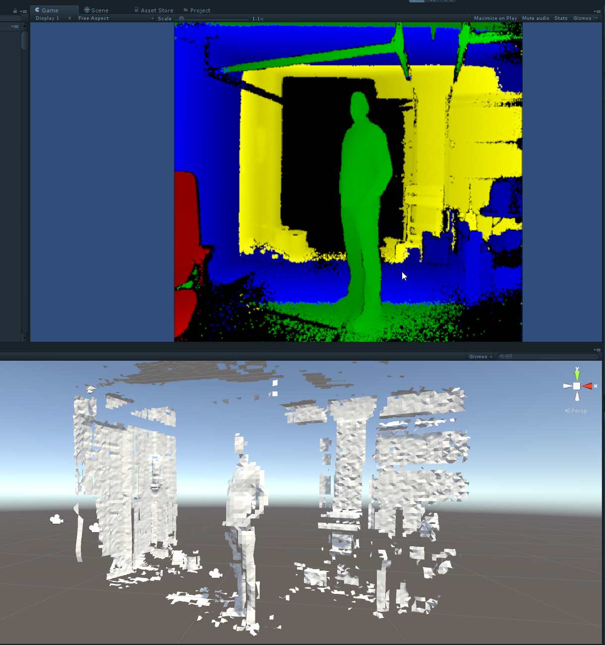
My friend Paul is doing his best Stalin impression, and you can almost make out his beer paunch.
Performance
SharpChisel performance
Essentially, the Chisel process iterates across every voxel inside the frustum of the depth image and asks the question “is this voxel near enough to count, inside or outside the surface”. It’s not a terribly difficult question to answer, but it does require a fair amount of work per voxel point:
- convert the voxel centre into world space coordinates
- transform these coordinates into camera space, then depth-image space
- use the depth-image coordinates to look up the depth at that pixel
- determine the depth and surface distance at that point
- if relevant, store this back into the voxel (with an associated confidence weight) or,
- Carve (remove) that voxel if it’s known to be empty now.
My initial dumb implementation took about three seconds to process the depth image into the voxel space. With a bit of data massaging and a little optimisation, I’ve got this under 300ms, which is decent, but still an order of magnitude slower than I’d like it to be. Ideally, I’d like to get this under 33ms as that would put me into the “realtime” space.
There’s a fair amount of potential optimisations in there, some that should be an easy day or two, and some that will require some really creative thinking. I’ve put one novel approach in there for chunk culling against the initial depth image which gave me a 100% speedup, and there’s a few more things I’d like to try in the coming weeks.
The main issue is the sheer number of voxels - each chunk is 4K voxels, and the scene I’m representing has about 1000 chunks in it. Most of these are empty, but I’m still doing math on about 1.7 million voxels and the world-space to camera-space conversion is a big part of this.
Marching Cubes performance
The marching cubes process has to run through every voxel, potentially 8 times, and then create a set of triangle meshes. Running this across the whole scene post-scan is taking about 800ms right now, which is no-where near realtime, but it’s under a second, so a good starting place. I then have to take the resulting mesh and convert it over to Unity, which is pretty fast (on the order of 5ms).
Next week
Next week, I’m going to try and get the scanning and meshing running in under 200ms, at which point I’ll be able to do this “realtime” at a 5hz rate.
If I get that working, I’ll look at taking the colour camera feed from the kinect and texturing the mesh (the same way I do it with the Tango) such that I’ve got a live feed on the data.
Next after that is getting the Kinect camera moving around the world, ideally positionally tracked (maybe using the Vive wand, although there’s always the option of getting LSD-Slam or ORB-Slam working).
Next after that, is going to be aggregating multiple feeds - so any arbitrary depth feed can be used as a source, and any arbitrary colour camera feed can be used as a source, and they all feed into the data set.
If I can get that working, then I’ve got a product (any maybe it’ll be time to get a team together).
If you can’t tell - I’m very excited ;) This may look like some retrograde steps, but I own the code from start to finish now, and I finally understand what it’s all doing.